
Induction heating
Induction heating
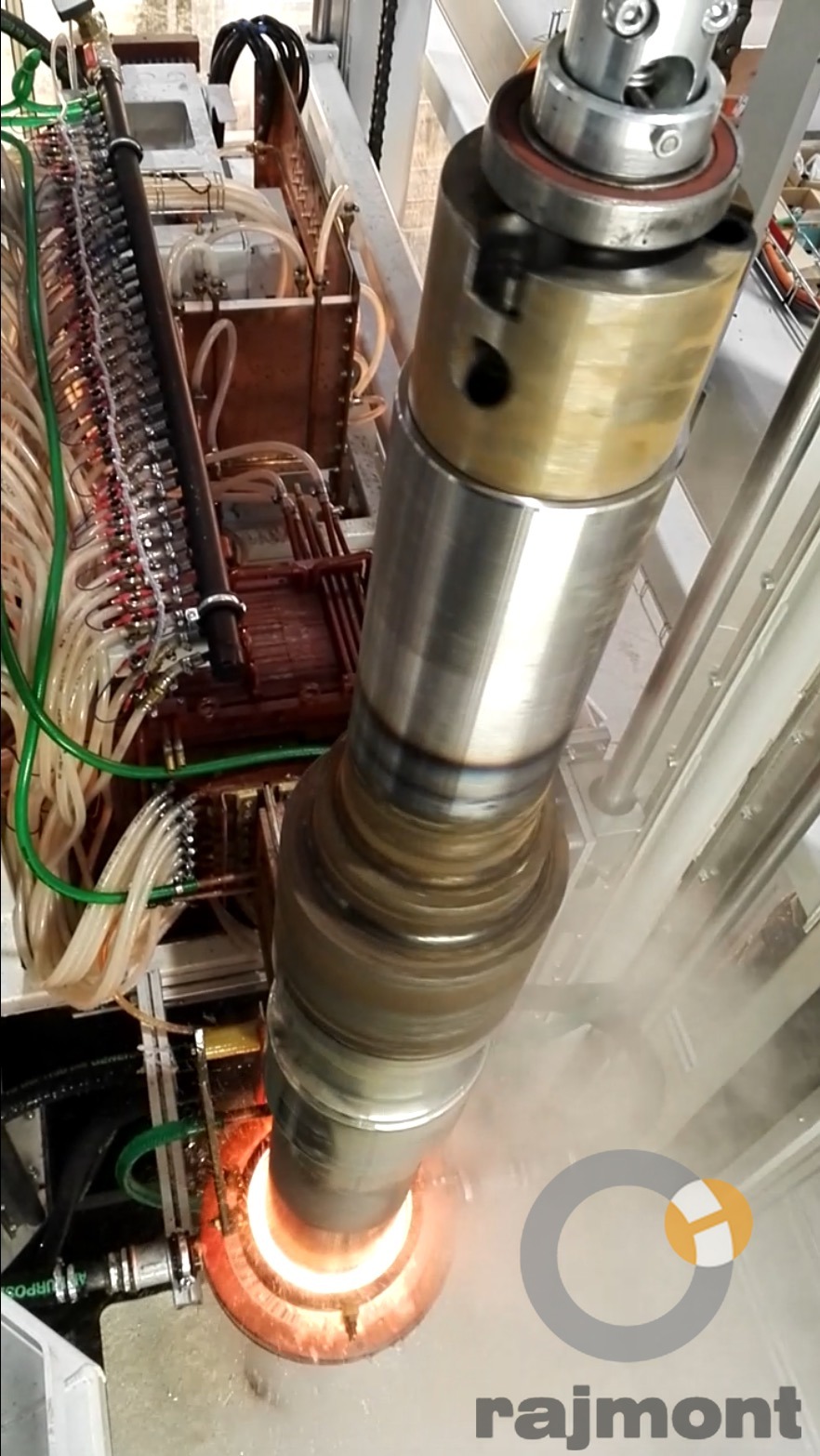
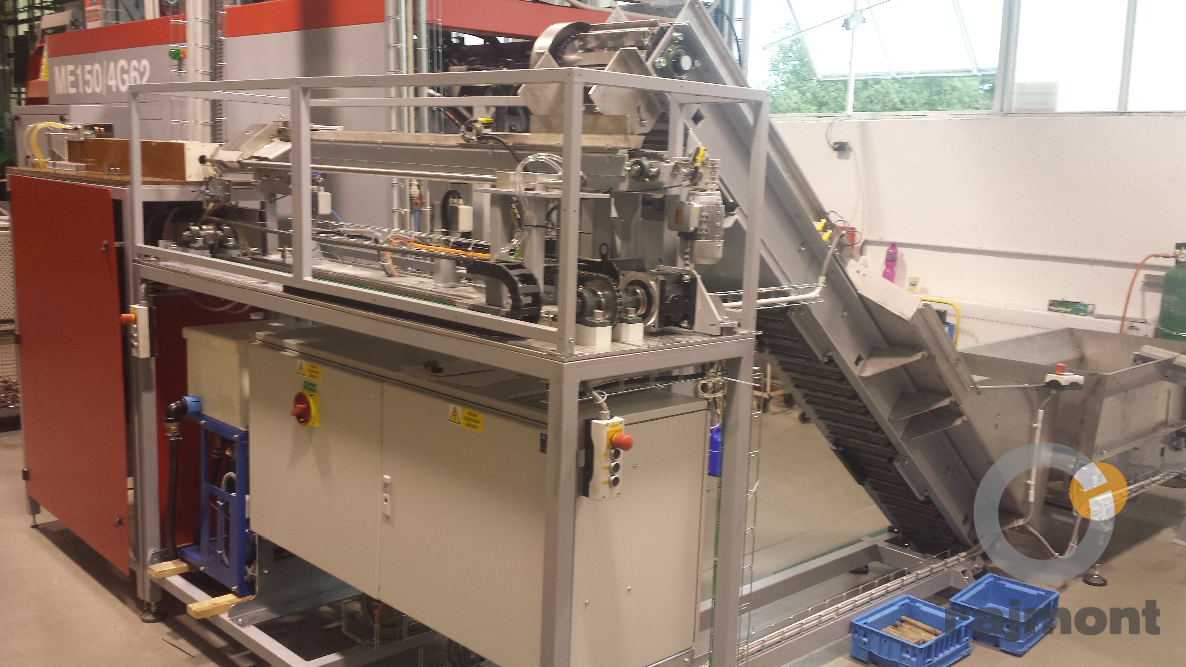
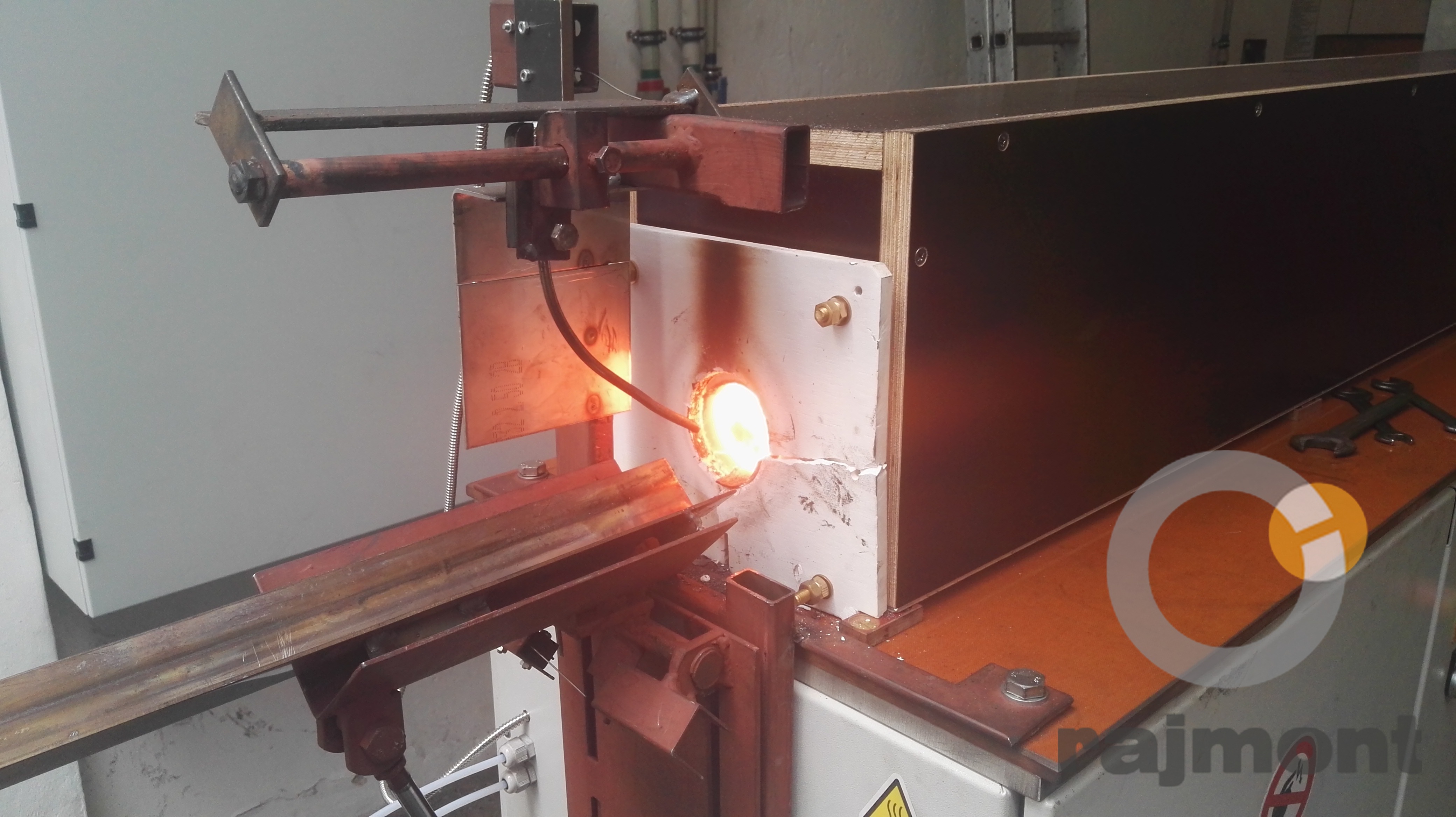
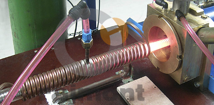
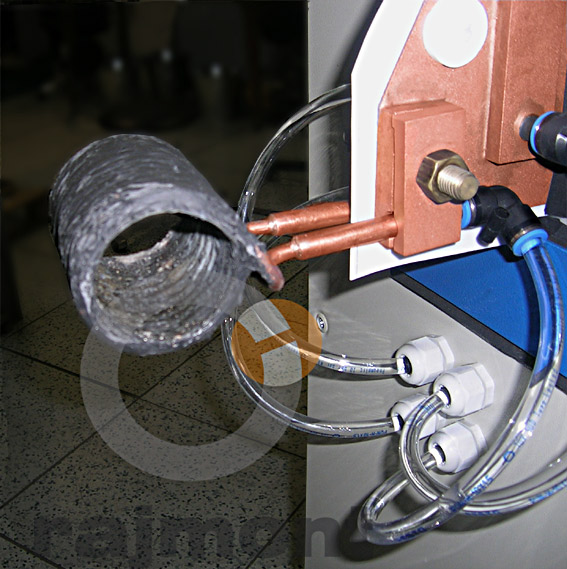
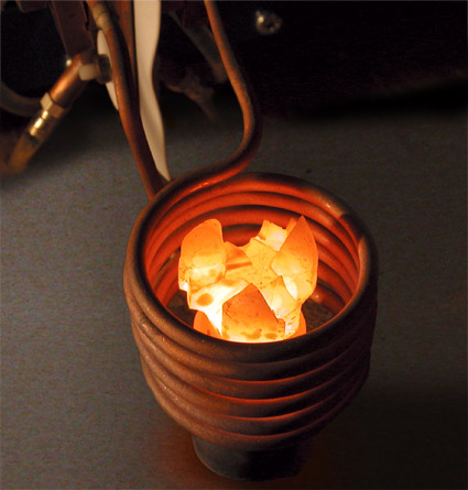
Rajmont s.r.o. has developed and supplies high-frequency and medium-frequency power sources for induction hardening, induction heating, induction soldering and induction welding in a wide power range to cover demand across the entire spectrum of production technologies.
(1).jpg)
Brochure - induction heating in a protective atmosphere
Basic range of generators for induction heating:
|
Generator type |
Power [kW] | Frequency | Cooling water consumption |
| HFR 15 | 15 | 50-500 kHz | 10 Lt./ Max. 25°C |
| HFR 22 | 22 | 50-500 kHz | 15 Lt./ Max. 25°C |
| HFR 50 | 50 | 50-500 kHz | 40 Lt./ Max. 25°C |
| HFR 80 | 80 | 50-500 kHz | 70 Lt./ Max. 25°C |
| HFR 100 |
100 | 50-500 kHz | 90 Lt./ Max. 25°C |
| HFR 150 |
150 | 50-500 kHz | 120 Lt./ Max. 25°C |
| HFR 200 |
200 | 50-500 kHz | 150 Lt./ Max. 25°C |
| HFR 250 |
250 | 50-500 kHz | 170 Lt./ Max. 25°C |
| HFR 300 |
300 | 50-400 kHz | 210 Lt./ Max. 25°C |
| HFR 350 |
350 | 50-400 kHz | 250 Lt./ Max. 25°C |
| HFR 400 |
400 | 50-400 kHz | 280 Lt./ Max. 25°C |
Basic range of medium-frequency generators for induction heating:
| Generator type |
Power [kW] | Frequency | Cooling water consumption |
| SFR 100 |
100 | 5-50 kHz | 50 Lt./ Max. 25°C |
| SFR 150 | 150 | 5-50 kHz | 70 Lt./ Max. 25°C |
| SFR 200 | 200 | 5-50 kHz | 90 Lt./ Max. 25°C |
| SFR 250 | 250 | 5-50 kHz | 110 Lt./ Max. 25°C |
| SFR 350 |
350 | 5-50 kHz | 150 Lt./ Max. 25°C |
|
Generators can also be supplied as standard in other power and frequency ranges. |
|||
Reasons to use high-frequency and medium-frequency generators for induction heating
- no contact is required between the processed material and the coil
- high power density and heating speed
- good control of metal temperature
- precise definition of heated zones
- simplicity of operation
- great flexibility of regulation
- good efficiency
- good working conditions and minimal negative environmental impact
In terms of efficiency, induction heating is an order of magnitude more energy-efficient than a continuous gas or resistance furnace. For example, a 100kW continuous furnace used for heating steel parts can be replaced by a 25kW high-frequency generator, which locally heats the workpiece within a matter of seconds, simply because the energy required for heating is directed exactly where it is needed.
Advantages of fully transistor-based HFR generators for induction heating
Using a fully solid-state HFR design (MOSFET and IGBT transistors) brings the following advantages:
- high efficiency - 90%
- modern MOSFET and IGBT technology
- theoretically unlimited service life - transistors do not age
- roughly half to one third of the installation footprint
- low cooling water consumption
- instant ramp-up to full power
- up to 1000x cheaper repairs in the event of a failure
- permanently stable operating parameters – ensuring production repeatability
Galvanic isolation of the HF generator from the mains supply is essential above all to suppress currents during earth faults between the inductor and exposed metal parts of the surrounding equipment. It also protects the generator operator in the event of unintended contact with the inductor – typical in soldering applications. A so-called mains isolating transformer is commonly used for galvanic isolation from the mains. However, its isolating effect is almost zero at frequencies in the hundreds of kHz due to the excessively high mutual winding capacitance, which is in the order of units of nanofarads. Optimal galvanic isolation can be achieved using a switched-mode power supply with a pulse transformer, which also brings further advantages in the form of a better power factor, excellent efficiency, minimal dimensions and, above all, a fraction of the weight of the conventional solution (e.g. a 15kW three-phase transformer typically weighs 170-200kg, whereas an equivalent switched-mode supply weighs about 20kg).
The newly developed switched-mode DC supplies are also delivered separately according to customer needs. Reference customers for the switched-mode DC supplies include SIEMENS.
PC visualisation of the HF generator
Visualisation of technological processes is nowadays a very well-known matter and needs no lengthy introduction. In this case we have many years of experience in the design and implementation of production lines for automotive wires and cables, where visualisation is essential due to the need for production monitoring. To meet this requirement we use the well-known and universal visualisation software ControlWeb from the Czech company Moravské přístroje, and for international customers WinCC from SIEMENS.
Operating data logging system
Existing HF HFR generators include operating data monitoring. Operating and fault states are recorded as a text file on a connected computer. The computer is in constant communication with the HF generator, and whenever any monitored parameter changes by more than 3%, everything is recorded. These operating data currently serve primarily for analysing the working conditions of HF generators in practice. The aim is to monitor the generator electronics data for quality evaluation, production management and service operations. Of course, there is also the option of remote transmission of operating data via the internet or a GSM gateway.
Cooling circuit with heat exchanger
To ensure heat removal from the internal parts of the HF generator, we developed our own internal cooling circuit using demineralised water with a heat exchanger, through which the customer can provide cooling. This guarantees long-term constant quality of the cooling medium without the risk of limescale and other impurities. The parameters and design of this system are consulted and optimised externally with the relevant specialists with a view to minimising installation dimensions and ensuring long-term reliability.
Disadvantages of vacuum-tube generators for induction heating
At present, the vast majority of high-frequency induction heating in the Czech Republic is performed using old vacuum-tube generators from the 1960s, 70s and 80s. These are mainly products of the ZEZ Rychnov n. Nisou company (GV series), based on tubes from the then Czech manufacturer Tesla Vršovice, produced in series of hundreds. In some cases you may also come across vacuum-tube HF generators from SIEMENS (production definitively ended in 1993) or the Swiss BROWN&BOWERI from the late 1960s.
Apart from the now critically severe shortage of spare parts – above all high-voltage capacitors, transformers and, to some extent, the tubes themselves – there are also problems with the presence of high voltage (up to 30kV) and very low efficiency, which theoretically approaches 60% (in reality 40 - 50%). The rest of the electrical energy is converted into heat, which must be removed from the tube generator area by additional systems. In the case of water cooling, which is used almost exclusively here, the re-cooling of the circulating medium and its excessive consumption must also be addressed. A vacuum-tube generator must be "ramped up" slowly, i.e. the tube heated for tens of minutes, which causes production downtime. In the event of a tube failure, which will always occur (given the principle of its operation), a new one must be procured, the purchase cost of which often amounts to 2/3 of the price of the entire generator and runs into tens, or more likely hundreds, of thousands of crowns. A tube also ages during long-term storage, shortening its service life without ever being used in operation.
Photos
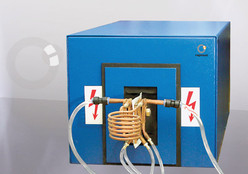
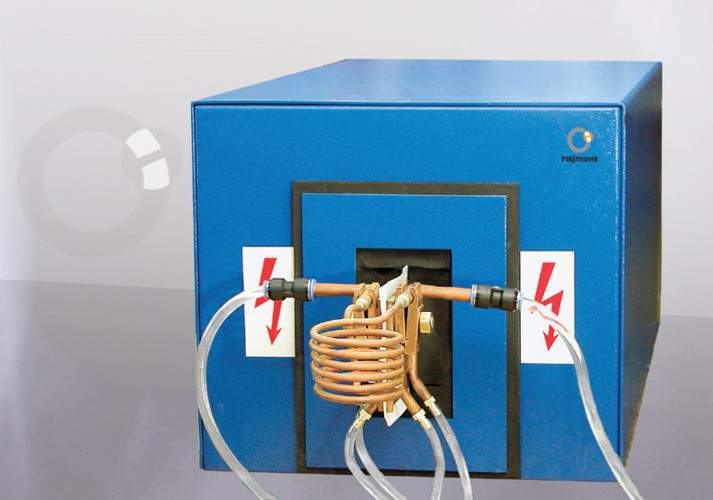
HFR25 generator
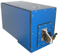
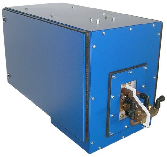
HFR50 induction heater
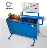
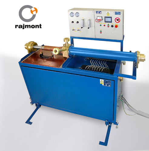
Induction annealing
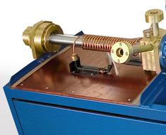
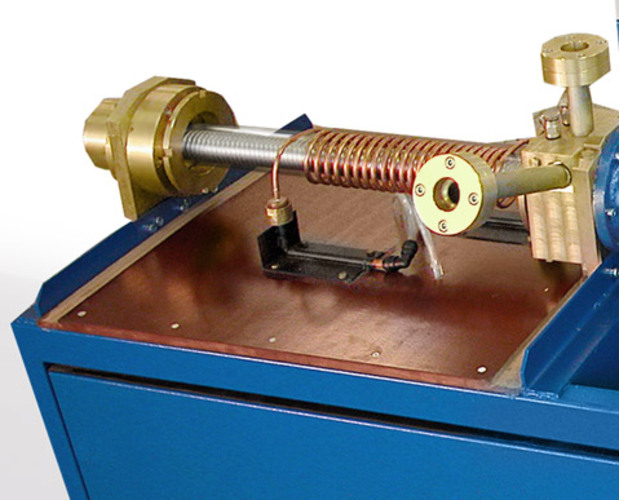
Induction annealing - detail
Enquiry form
Go to: ↑ Content ↑ top of the page ↑ homepage ↓ search ↓ navigation


